Whether it be through new inventions, technological advancements, more efficient processes, or simply finding better and easier ways to do things, the way we work is evolving. In the power industry, we have evolved to create smart grid technology to understand the real-time needs of the network. In the telecommunications industry, we have evolved through hardware advancements to produce faster bandwidth capabilities and, by using artificial intelligence, anticipate and proactively address potential outage locations before the end user is impacted. The planning, designing, and documenting of these networks is also evolving to allow further access and knowledge of the networks that we deploy. As we deploy the advanced networks that are being constructed today, the management of these networks requires a different level of access and information.
As we continue our discussion, my question for you is, is CAD the ultimate solution?
 Let me begin unpacking my question and first acknowledging that CAD software has radically changed and advanced the utilities industry. Prior to CAD software being readily available, the workforce to perform drafting was extremely scarce and the skill required to manually draft was truly a skill. The introduction of CAD software expanded the workforce greatly as it allowed a different subset of people to enter the drafting workforce. So, my question is in no way to convince you to alienate your CAD system, but potentially provide insight on how to align your CAD usage in a different way. The question here is more along the lines of other advancements that we have seen such as: the telephone replacing the telegraph; the computer replacing the typewriter; email replacing faxes; the iPhone replacing the Blackberry; fluorescent/LED bulbs replacing incandescent bulbs (don’t get me started on this one – BRING BACK MY INCANDESCENTS); lastly, CAD software replacing manual drafting. All these items introduced newer technologies and ways to accomplish the same tasks, just in a different, more efficient way.
For decades, CAD software has been utilized to document the planning, designing, permitting, constructing, and as-built documentation of network deployments. While this process has worked, is it the best way, really? My response there would be, it depends.
My background is natively in the telecommunications industry, so I am going to focus the next portion of our discussion towards the normal practices for telecom. However, I am sure that there are parallels in other utility lines of business. Traditionally, CAD packages have been generated from scratch to plan a network. Drafters have started by creating land base data such as right of way (ROW), edge of pavement (EOP), back of curb (BOC), and street centerline (CL). In some cases, public record information is compiled to include parcels, address data, and easement information. Once these items are accounted for, we now move on to existing utility information that is compiled by manual field collection and documenting above ground features such as poles, power equipment, water meters, telecommunication boxes, etc. All these items are manually represented within the CAD package being created. We plan our network, input stationing information, offset data, cut the package into sheets, generate match lines, and package the CAD package into a PDF sheet set that is then used for permitting and construction. Once construction is complete, the PDF is returned with handwritten notes for as-built updates that are manually performed within the CAD package. In most cases, the CAD package is saved and filed as a standalone record that is not consolidated into a master file for network documentation. What happens when a different drafter needs to plan a network expansion in the same area? What happens when a neighboring area is designed? Are the networks “stitched” together to create a connected network? All of this depends on the workflow and processes by the companies deploying the network.
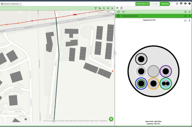
From my experience, if utilizing CAD, coupling it with a dedicated, spatially driven network management system is the better solution. For example, 3-GIS | Web, a GIS-based fiber network management system, allows for all data to be stored in a single system of record for all users to see and interact with, whether it be one small network area, or a larger dataset (such as that of a Tier 1 provider). We referenced a single CAD package being created earlier where the user created land base data, public record information, existing utilities, and then the proposed network. What if all the data mentioned was generated automatically using GIS? The data could be permanently stored in a single source where the same land base, public record, and existing utility information could be referenced for future use, preventing the need for recreating the data. For as-built updates, the original planned network source data is available for modification and updates, while allowing for feedback from field crews through inspection checklists or notes within a mobile application rather than handwritten notes on a PDF document.
What about permitting and workprints?
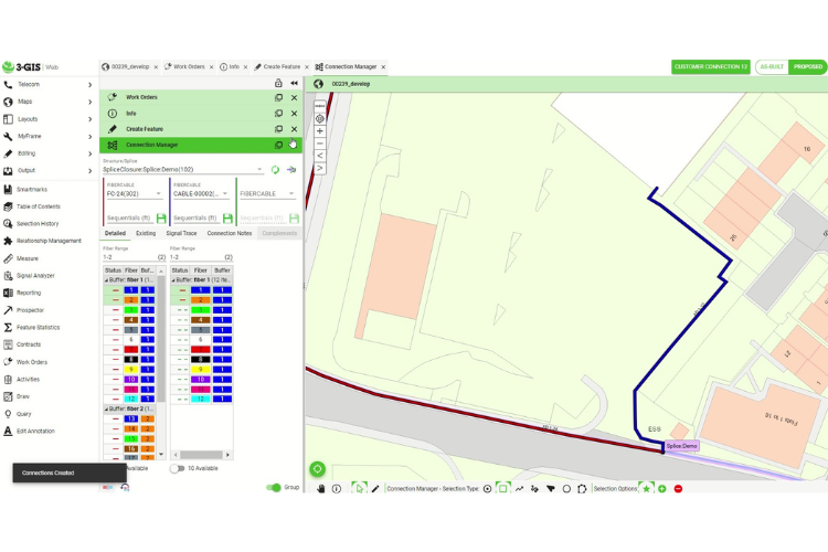
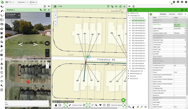
Permitting is the one area that seems to have been most cemented using CAD. However, using a GIS system allows permitting agencies to visualize proposed networks in a geospatially accurate manner that quickly can be layered with supplementary data. Through configuration, a fiber network management system, using 3-GIS | Web as an example again, may be configured to provide network details required for review. Stationing? Check. Offset measurements? Check. Dimensioning? Check. Structure sizes? Check. Conduit, duct, or cable sizing? Check. All right there in the same system, available through attribution labeling. For ease of access and visibility, the same data can easily be exported through .gdb, .kmz, or .shp, all while using the same system as the source.
Likewise, workprints can be configured and produced directly from the same system. Every workprint is consistent and produced just like the prior. The consistent and system generated format eliminates error and prevents inconsistency between documents.
What if I want to maintain my CAD outputs?
Seek a vendor that can easily collaborate with you to develop workflows to meet this need, while maintaining the fiber network management system (i.e., 3-GIS | Web) as the single system of record. Modifications to the design occur in 3-GIS | Web, the CAD template is set up to ingest the 3-GIS | Web output, and the template is repopulated by simply modifying the source files associated with the work area.
In closing, as we continue to push the envelope through technological advancements in network infrastructure, real-time up to date access of geospatially accurate data will be required. The CAD processes of the past do not support this level of documentation or real-time system of record. However, interoperability between systems allows users access to geospatially accurate data while providing CAD integration to meet the needs of today. So, is CAD the answer? Alone, probably not. But, through the right integration, it can be.