This series is centered around technologies and methods being developed for network densification projects as communities across the world prepare for the 5G revolution. This push for higher speeds and lower latency has driven the creation and implementation of many new technologies and construction trends that will allow for easier deployment of fiber networks. The first trend we discussed was the use of micro-trenching in infrastructure construction. If you missed that post, you can read it here. This week, we’ll discuss the use of collapsible ribbon and 200µm cables.
The background
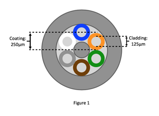
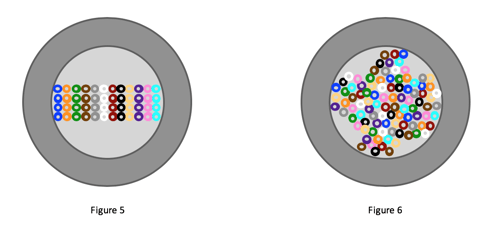
Standard dimensions for single-mode fiber cables have remained virtually unchanged since their introduction in the 1970’s. Such cables traditionally feature a core size between 8-10 microns, cladding size of 125 microns, and a coating size of 250 microns (see Figure 1 below). The way in which these individual fibers have been bundled together has remained fairly consistent over the years as well. Conventional flat ribbons are traditionally placed together in a linear fashion, creating, as you could imagine, a lot of wasted space in a round cable (see Figure 5 below). Though having this standardization benefited the industry for many years, the transformation of our world’s connectivity demands requires a transformation in the technologies used to provide said connection.
200 micron fiber
Moving from the traditional 250µm coated fiber cable, to the 200µm cable, creates a size difference of roughly 36%.
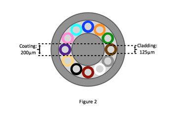
You can imagine that decreasing the size of the outer coating of each individual cable would allow for more of those cables to fit inside a larger cable. On average, taking the coating size of each fiber from 250µm to 200µm allows for twice the amount of fibers per larger cable. This not only reduces the weight of the cables, easing installation, it also reduces the total amount of cable needed to connect a certain area.
Because there is more available fiber in each cable, construction crews are able to lay less cable, but provide more fiber. This can significantly scale down construction disruption, particularly in areas that require underground deployment. With these smaller cables, comes even smaller micro-trenches needed to bury them. If you also consider that fusion splicing can be accomplished with the same tools used with conventional 250µm cables, and that the 200µm coating remains consistent with protection regulations, the benefits of the smaller coating are even greater.
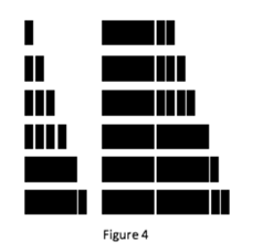
The greatest challenge that has risen from using 200µm coated fibers is due to the fact that so many more fibers can fit within the cables, the distinguishing of the fibers had become complex. Though the traditional color coding is still prevalent, in cases where there are too many fibers and not enough colors recognized industry wide (typically any more than 18 fibers), a new code is necessary. The most often employed method is marking. In the field, this means a certain number of lines is printed on each individual fiber, similar to tally marks. 3-GIS | Web ensures that the marked fiber in the field is correctly documented in the system through the Connection Manager tool, which allows you to trace and manage connections to/from each individual fiber.
Collapsible ribbon
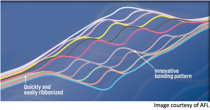
Similar to the 250µm coating, the physical attributes of the fiber cables themselves have remained very consistent over the years as well. As noted above, conventional fiber, placed linearly inside of cables creates a lot of wasted space inside the cable. Because of this, more cables are required to provide more fiber. If we look at Figure 6 however, it is evident that there are more individual fibers in the larger cable. Twice as many in fact. This is because the fibers in Figure 6 represent collapsible, also called rollable ribbon fiber.
The obvious benefit to using collapsible ribbon is fitting more fiber in each cable, therefore decreasing the amount of cables needed to serve an area - similar to the benefits of the 200µm fibers. What is not so obvious however, is that in using collapsible ribbon, installers and technicians can perform faster mass fusion splicing - meaning they can splice numerous fibers at the same time even easier than with conventional fiber. This in turn greatly reduces the installation time and costs, as well as allows for quicker restoration if there is an outage, particularly if you utilize 3-GIS | Web’s OTDR trace tool which allows you to geolocate an outage from a specific fiber equipment or splice closure.
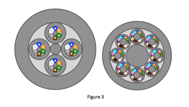
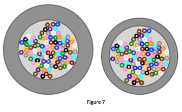
Individually, we can see that each of these alternative fiber options provide great benefits, but as Figure 7 shows, combining the two produces even further advantage. If each fiber was collapsible ribbon fiber surrounded by 200µm coating, the cost savings and space savings would increase exponentially.
With these and the many other new technologies and fiber improvements we’ll be discussing in following weeks, bringing fiber to your city could become easier, faster, and cheaper. With the number of components requiring a connection - whether its autonomous vehicles, speed bumps, road signs, medical devices, or houses and office buildings - continuing to increase as Smart Cities and IoT become more of a reality, and the constant demand for faster speeds, fiber is the only valid network option for communities striving for 5G connectivity. And with that much fiber needed, the question then becomes: can your network management system handle everything?